The Role of QFD in Systems Engineering
Michael J. Mangieri
University of Maryland University College
Graduate School of Management & Technology
Abstract
This paper examines the applicability of a Quality Function Deployment (QFD) program within systems engineering. An analysis of using QFD throughout the phases of systems engineering was made to show how customer involvement can be achieved in each stage of system development. An examination of the application of QFD as the basis of a system’s quality plan and quality design process was made. It was shown that the application of QFD provided a formal means to facilitate customer involvement during the early stages of system concept. QFD was shown to be an effective means for integrating quality into product development. In addition, QFD was also shown to be a useful framework for identifying the “whats” and “hows” of system reliability issues. In conclusion, the addition of QFD throughout the stages of the systems engineering life cycle makes it more likely that customer concerns and demands are captured, documented and ultimately incorporated into the final product. Use of QFD, although time consuming and tedious, can be a major means to achieve customer satisfaction. QFD should be one of the tools considered by every system engineer as a means to prioritize and focus the system engineering process.
The Role of QFD in Systems Engineering
In his best selling book, Decline & Fall of the American Programmer, Ed Yourdon (1993) claims that for American software firms to keep hold of their dominance in the software industry, they need to become world-class organizations and not just run-of-the-mill. He makes the distinction between the two organizational types by claiming three comparisons: the cost of the staff in terms of salaries and benefits, the productivity of the staff, and the quality of the systems developed. Indeed, of these three, quality plays a vital role in the acceptance of new systems. Yourdon (1993) succinctly points out that software systems containing lots and lots of code are worthless to a customer if the software does not work, is not easy to maintain or modify, or can not be trusted. But what is quality? How is it defined?
American manufacturers use the typical measures of number of defects, MTBF, rework cost, etc., as indicators of product quality (Schaefer, 1995). Yet these measures only show defects in a product after production; they provide limited (if any) useful information about the process used in the production of that product that may have contributed to its defect. As an illustrative point: it is not the function of a brake to squeal, and therefore, neither efficient nor effective for engineers to measure squeal in order to reduce it (Schaefer, 1995). Furthermore, measurement of quality in this way avoids another aspect of quality that needs to be addressed, and that is the customer’s viewpoint. How does our customer view quality?
James Bach (1996) offers the following insight into what customers feel about quality when he states, “...our clients, whether internal or external, will never know the quality of our products. They will form a perception of quality and act on that basis, whether or not that matches our perception.” David A. Garvin (as cited in Day, 1993) discusses abandoning the view of measuring parts and managing defects when he states, “To achieve quality gains, I believe managers need a new way of thinking, a conceptual bridge to the consumer's vantage point ... high quality means pleasing consumers, not just protecting them from annoyances.” Juran and Gryna (1993) speak of the customer as fitting into one of three classifications for the purposes of planning for quality: those that are interested in purchase price as equal to or more important than quality, those who evaluate competing products in terms of cost and quality, and those who simply “want the best.”
Therefore, the extrinsic factors (i.e. the view of the customer) are needed to fully determine the true “marketability” of a product, and what is desired is a means to evaluate the quality of a product as it is being developed, a way to incorporate the view of the customer in our system designs.
An infusion of Quality Function Deployment, or QFD, into the systems engineering process is one way to achieve this goal.
Overview of Quality Function Deployment
The concept of QFD, which is a combination of the ideas of Deming, Juran and Taguchi, was introduced in Japan by Yoji Akao in 1966. The actual Japanese name for the methodology is hin shitsu, ki nou, ten kai. Translating into English is difficult since the terms have multiple meanings. The best translation is Quality Function Deployment (see figure 1). QFD is designed to help organizations understand the customer’s requirements, prioritize them, and respond to them in an organized way. QFD is a way of listening to the customer. Using QFD, system developers are forced to answer the following three questions: 1) What are the qualities the customer desires from the product, 2) what must the product do (what are the main functions of the product), and 3) how can we as the developer, considering resources available, best provide what the customer wants?
|
|
|
Figure 1. QFD name in Japanese (Guinta and Praizler, 1993, p. 5) |

QFD is not a tool. It is a planning process. It assists the development organization with achieving a customer focus, and a thorough understanding of what the customer desires.
QFD Paradigm
In order to use QFD effectively, systems engineers need to understand that QFD is a paradigm shift from the way they may have typically done business (Guinta and Praizler, 1993). It requires a different mind-set for developers, one of customer involvement, from the initial requirements phase, through design and ultimately to the final production of a product or service. Guinta and Praizler (1993) claim that nearly 80% of life-cycle costs are locked in during the design phase. By utilizing QFD in a life-cycle development methodology, defects can be captured early in the design phase, where changes are less costly and easier to manage. This could reduce the amount of change required in the later stages by 70%.
The QFD paradigm shift is a concept that encompasses a new thinking about quality and tradeoffs. Instead of inspect-in quality, via standard quality control practices, a design-in quality focus is employed. Measures of quality must express the process used and the relationship between the design of the product and the customer’s wants and needs. It is the engineering intent of the product to which customer’s will respond (Schaefer, 1995).
Then there are the tradeoffs faced by businesses regarding quality, time and cost. Whenever a decision to increase quality is made, a tradeoff is often necessary. One could increase quality by spending more money, or lower cost by simplifying process or cheapening the product, or spend more money to speed up the process or omit steps in the process, thereby getting product to market sooner. According to Quinta and Praizler (1993) Americans follow a design philosophy that consists of three principles: everything is important, manage the tolerance stackup and react to customer problems. The Japanese follow a different philosophy. Theirs includes an effort to decide what is important, they design to reduce variation and they strive to optimize the product. It is the first principle of the Japanese philosophy that is the center of the QFD paradigm, deciding what is important.
Before moving to the discussion of how to incorporate QFD in system engineering, it is necessary to briefly discuss the tool of QFD, the “House of Quality".
The “House of Quality”
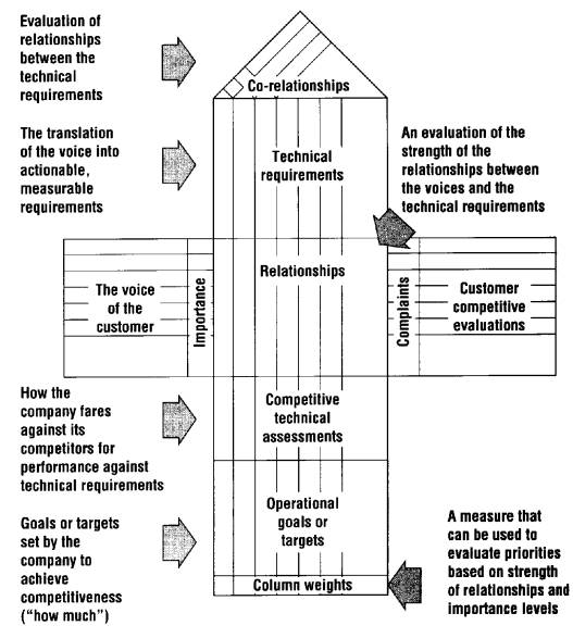
Developed by John Hauser and Don Clausing (1988), the House of Quality (HOQ) is the basic tool used in the QFD methodology. Created as a matrix-style chart, it helps designers identify customer needs and desires, shows the tradeoffs among these desires and the design features that are built to accommodate them, and benchmarks the quality of the product in terms of relationships to customers requirements and final product attributes. Although too detailed to discuss at length here, a summary in the basic use of the HOQ is described below.
As illustrated in figure 2, there are two major parts of the HOQ. The horizontal matrix at the house’s center contains information pertaining to the customer. These are the customer attributes, the whats and the customer perceptions, the whys. The vertical portion deals with the technical processes and information that is used to respond to the customer’s needs. It includes the engineering characteristics, the hows and the objective measures and targets, the how muches. Basically the chart forms a conceptual mapping of the characteristics that the customer desires in the product (the whats) and the engineering decisions that are made to achieve those desires (the hows).
|
|
|
Figure 2. The House of Quality (Day, 1993, p. 20) |
A typical QFD implementation moves through four sequential phases of a product development cycle: product planning, design planning, process planning, and production planning. For each phase, the previous phase’s hows become the new phase’s whats. As each house is visited, three steps are implemented:
1.Objective analysis - identify with the customer, their requirements, and the goals of the development team.
2. Determine the Whats - what are the characteristics of the product desired by the customer.
3. Arrive at the Hows - ways of achieving the Whats.
Throughout the early phases of the systems engineering process, for example, the major inputs to the QFD planning matrix are the customer’s wants and needs, which in QFD parlance is called the “Voice of the Customer”. These documented needs are traced throughout the process and all team members (analysis, design, code) are able to see how their inputs contribute to satisfying customer requirements. All decisions can be linked back to customer requirements. It is through this planning process that an organization develops a vital customer focus.
QFD in Systems Engineering
How does QFD fit into the systems engineering process? In order to answer that question, a concise definition of systems engineering is needed as well as a framework, or model, with which to show the incorporation of the elements of QFD. There are many definitions of systems engineering, but Blanchard (1991) provides an interesting description of systems engineering that incorporates a central concept of QFD. He states that system engineering is not an “engineering discipline” in itself, but “ ... system engineering involves the efforts pertaining to the overall design process employed in the evolution of a system from the point when a need is first identified, through production and/or construction and the ultimate distribution of that system for consumer use. The objective is to meet the requirements of the consumer in an effective and efficient manner.” Blanchard makes a point of identifying the role the customer plays in the overall engineering effort. The ultimate goal is to satisfy the customer. System engineering by itself is a type-specific methodology used in the development of products, and incorporates a complete requirements and design methodology. System engineering emphasizes completeness; while QFD emphasizes focus (Bicknell and Bicknell, 1993).
Why the emphasis on focus? Following the steps of system design and development a great deal of iteration and re-thinking can occur in both the Preliminary System Design and Detail Design and Development phases. Even at the onset of conceptual design, while feasibility studies are undertaken, technical performance measures are established, system operational requirements are determined, and the maintenance and support concept is developed, much discussion of alternative designs and feedback with the customer may take place. As a result of this effort, without focus, the systems engineering process can be a costly and unmanageable model to follow. There are a number of criticisms of system engineering as a methodology, some of which are listed here (Bicknell and Bicknell, 1993):
1. Lack of ability to prioritize requirements early in the design
2. No mechanism to show visibility into the interrelation of competing subsystems
3. Process is cumbersome - lots of people involved; many communication paths
4. Iterations are often of a repeat nature vice a refinement nature
5. Development of specifications often done in a “vacuum”
6. System engineer becomes responsible for the design - no team accountability
QFD, as an integral part of the system engineering process, provides the focus that is necessary to solve many of these shortcomings.
QFD-integrated System Engineering Process
Where is QFD applied in the process? Bicknell and Bicknell (1993) have developed a nine step approach toward the integration of QFD with the standard system engineering process. As depicted in figure 3, this approach starts with the collection of customer needs and wants,
|
|
|
Figure 3. The nine steps of the Integrated QFD Approach. (Bicknell and Bicknell, 1995, p. 39) |
|
|
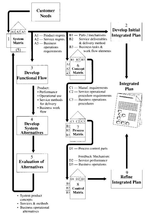
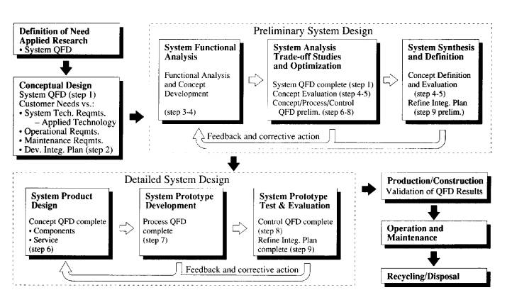
and through a succession of QFD analyses, leads toward the creation of a completed integrated plan, ready for use in the production of the designated system. By mapping this approach on top of the standard system engineering process, a new QFD-integrated process emerges (see figure 4).
|
|
|
Figure 4. QFD-integrated System Engineering Process (Bicknell and Bicknell, 1995, p. 202) |
Definition of Need
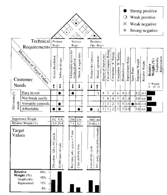
Blanchard (1991) proposes that the system engineering process starts with an identification of a need, which is based on a real or perceived deficiency. To prevent “technology-driven” products, an analysis of this need is undertaken including market analyses, applied research, and so on. The main focus is, of course, on satisfying customer requirements. A system QFD matrix is produced at this step of the process, with emphasis on the interaction of the customer requirements with product, service, and business operational requirements. This is necessary since customer needs are not simply related to product alone, but depend upon the service functions (such as technical support) and the activities of the business (product development process). Grouping the initial requirements into these three categories incorporates cross-functional analysis and involves all aspects of the system engineering life-cycle process. This also provides the means to focus on a particular area of requirements in the case where the scope of effort pertains to only one category or another. For example, an effort to establish a modification of an existing product may concentrate a great deal on the product category of requirements while maintaining a lesser focus on the business and service sides of the system matrix. When the system matrix is completed, it addresses the prioritization of customer requirements, the relative ranking of the technical requirements, the target values for the technical requirements and the correlation among all the technical requirements. As an example, figure 5 represents a typical system matrix for a video game. The end result of this step in the process is to produce a complete set of initial system requirements.
|
|
|
Figure 5. Sample System matrix (Bicknell and Bicknell, 1995, p. 116) |
Conceptual Design
The next step is the recommendation of a design approach to be used in the development of the product. During this step, various proposed designs are examined for feasibility, the most likely candidates are selected, and a preferred approach is agreed upon. Bicknell and Bicknell (1995) suggest an integrated plan be developed to guide the implementation and track the progress of the project after the initial requirements and system matrix have been completed. This plan is the method by which the QFD team assigns and takes responsibility for completing the project tasks in an orderly and controlled manner. The plan becomes the glue that holds the system engineering process together and helps define the interfaces between subsystems and create avenues of communication among the various departments involved in the engineering effort. The results of the conceptual design step lead directly to the creation of system operational requirements and maintenance requirements.
Preliminary System Design
There are three major sub-steps within the preliminary system design step: system functional analysis, system analysis trade-off studies and optimization, and system synthesis and definition. During the second sub-step, with the system matrix complete, the next level of QFD is developed translating the initial requirements into product, service and business operation requirements. This results in a concept matrix that incorporates product performance, operational use, service methods for delivery, and business work flow. There is much feedback and corrective action taking place within these three sub-steps, with the ultimate goal of producing a single system that best meets the customer needs. Three matrices are ultimately developed at this stage: the concept matrix (already described), a process matrix, and a control matrix.
The process matrix is developed by copying the top portion of the system matrix (the product performance, operational use, service deliverables, and the business operational tasks/work flow elements) and placing it on the left of what will be the new process matrix (the whats). These new derived requirements are mapped against the manufacturing procedures, service operational procedures, and business operation procedures to arrive at a set of hows, or the engineering characteristics, that can meet these requirements. Likewise, the process is repeated once again to produce the control matrix, whose function is to determine the process and feedback mechanisms necessary to ensure that engineering procedures are followed and measured (see figure 6). At this point in the process, the concept, process, and control matrices have been created, but are still incomplete. Through the feedback loop they are refined but will still remain as preliminary versions until the next step, the detailed design step.
|
|
|
Figure 6. The House within the House (Carter and Baker, 1991, p. 62) |
Having these matrices initially completed at the preliminary system design step, provides a convenient mechanism for identifying key areas of reliability concerns, maintainability issues, and other technical problems that may significantly impact schedule and cost, as well as the overall quality of the final product. Finding these potential problems early in the system engineering life-cycle reduces cost and overall schedule time. Finally, the integrated plan is updated to reflect the decisions made during preliminary system design and during the analysis of the three HOQs.
Detailed System Design
The detailed system design phase contains another three sub-step and corresponding feedback loop. Its purpose is to finalize the three matrices produced in the previous step. During system product design, the concept matrix is completed. Any parts or components are now fully identified and services required are documented. In the system prototype step the process matrix is completed. System process and procedures used throughout the remaining portion of the system engineering process are refined as the prototype is evolved. Finally, at the end of the system prototype test and evaluation phase, the control QFD is completed, the formal test and evaluation of the system is initiated to determine if the design meets the target specifications, and the integrated plan is finalized. Note here that the final feedback loop is for further refinement of the design, not a “back-to-the-drawing-board” activity (Bicknell and Bicknell, 1995).
While all this seems a bit much, keep in mind that the goal is to track customer requirements throughout the life-cycle of system development. If the QFD implementation is integrated and executed properly, the technique will provide the focus on implementing the prioritized elements documented in the matrices, while the basic system engineering process provides the required steps, procedures, and methods to carry them out.
Benefits
Using QFD in the systems engineering process provides a much more effective way of doing the traditional activity of product planning (Clausing, 1994). By eliminating much of the rework that is typical in a development project, QFD reduces total development time and shrinks time to market. Elboushi and Sherif (1997) claim, “Using the QFD process enabled us to capture requirements, produce specifications and designs that are faster by a factor of 50% compared with other classical methods; more robust by a factor of 60% with respect to identification of conflicting requirements or potential bottlenecks; and more consistent by a factor of 70%” (p. 143). Since it focuses on customer requirements, there is greater probability that the customer will be satisfied with the end product. Clausing (1994) points out that traditional planning disregards the voice of the customer and many times does not produce specifications that are adequate and precise. QFD overcomes these issues by emphasizing formats that carefully guide the planning process from the voice of the customer to corporate expectations. And by fostering multifunctional teams that work toward consensus, providing communication across all phases of the life-cycle, reliability goes up, maintainability is increased, and overall quality is enhanced.
Implementing QFD
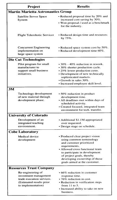
QFD, by its very structure, is time consuming and complex. It requires a detailed set of matrix documents, planning, active participation of all the representatives of the total life-cycle such as designers, engineers, manufacturing groups, sales personnel, marketing people, etc., and more up-front time during the early stages of product development. It involves coordination among team members, an agreement of what is to be done, and how, before becoming involved in the lower-level details of the design activities. Yet the payoff can be substantial if QFD analysis is properly conducted. Bicknell and Bicknell (1995) have collected a list of case study examples showing tangible results of using QFD (see table 1). In addition, they describe some of the intangible ones as well, such as improved interfunctional communication, improved management/employee relationships, true empowerment of employees, improved company morale, and development of a motivating team environment.
|
|
|
Table 1. Case Study Examples of Benefits Achieved (Bicknell and Bicknell, 1995, p. 34) |
Kenneth Crow (1996), President of DRM Associates has a few recommendations that he proposes to organizations just starting with QFD:
1. Obtain management commitment to use QFD
2. Establish clear objectives and scope for using QFD
3. Establish a multi-functional team
4. Obtain QFD training
5. Schedule regular meetings to maintain focus
6. Avoid gathering perfect data
Most of all, keep the emphasis on capturing and prioritizing the voice of the customer. Market surveys, focus groups, customer interviews, etc., are all time consuming and expensive but essential. QFD may rely on techniques such as benchmarking, failure-mode-and-effects analysis, value engineering, and the like, to best implement the customer’s requirements (Kinni, 1993).
Conclusion
QFD can significantly enhance the system engineering
process. As Blanchard (1991) reminds
us, one of the most important objectives of system engineering is to
“meet the requirements of the customer in an effective and efficient manner”
(p. 13). Integrating QFD into the system engineering process provides three
basic quality techniques that address the very issue of meeting customer needs.
QFD enables a company to focus on the voice of the customer. QFD is a method
for mapping and prioritizing customer needs and wants into product, service and
business operations in a way that both optimizes the organization’s process as
well as providing a means of meeting or exceeding customer expectations. And
QFD enables cross-functional communication, involving the whole organization in
developing a set of accurate requirements and integrating those requirements
into system designs. Theodore Kinni (1993) puts it plainly when he states,
“Simply put, QFD is work. On the other hand, its growing popularity indicates
that faster and less expensive development cycles, improved quality and
reliability, and greater customer satisfaction are well worth the effort” (p.
32).
References
Bach, J. (1996). The Challenge of Good Enough Software. [On-Line]. Available: http://www.stlabs.com/bach/good.htm
Bicknell, B. A., & Bicknell K. D. (1995). The Road Map to Repeatable Success. Boca Raton, Florida: CRC Press.
Blanchard, B. S. (1991). System Engineering Management. New York, NY: John Wiley & Sons, Inc.
Carter, D. E., & Baker, B. S. (1991). Concurrent Engineering: The Product Development Environment for the 1990’s. Manuscript submitted for publication.
Clausing, D. (1994). Total Quality Development: A Step-By-Step Guide to World-Class Concurrent Engineering. New York, New York: ASME Press.
Crow, K. (1996). Customer-Focused Development with QFD. [On-Line]. Available: http;//www.soce.org/Papers/CrowQFD/Crow-qfd.html
Day, R. G. (1993). Quality Function Deployment. Milwaukee, Wisconsin: ASQC Quality Press.
Elboushi, M. I., & Sherif, J. S. (1997). Object-Oriented Software Design Utilizing Quality Function Deployment. The Journal of Systems and Software, 38, 133-143.
Guinta, L. R., & Praizler, N. C. (1993). The QFD Book. New York, NY: Amacom Books.
Hauser, J. R., & Clausing, D. (1988, May-June). The House of Quality. Harvard Business Review, 5, 63-73.
Juran, J. M., & Gryna, F. M. (1993). Quality Planning and Analysis. (3rd ed.). New York, New York: McGraw-Hill, Inc.
Kinni, T. B. (1993, November 1). What’s QFD? Quality function deployment quietly celebrates its first decade in the U.S. Industry Week, 242, 31-32.
Schaefer, R. H. (1995). Educating Today’s Engineers. In W. E. Eureka, & N. E. Ryan (Eds.), Quality Up, Costs Down: A Manager’s Guide to Taguchi Methods and QFD (pp. 49). New York, New York: ASI Press.
Yourdon, E. (1993). Decline and Fall of the American Programmer. Englewood Cliffs, NJ: PTR Prentice Hall, Inc.