MIDI
Musical Instrument Digital Interface
A Communications Protocol
for Electronic Musical Instruments
Michael J. Mangieri
University of Maryland University College
Graduate School of Management & Technology
Abstract
The Musical Instrument Digital Interface (MIDI) protocol has been widely accepted by musicians all over the world. Created in 1982 and standardized in 1984 by the MIDI Manufacturers Association (MMA), MIDI provides an efficient, standard format for conveying musical performance data between MIDI-capable instruments and between MIDI instruments and computers. This paper will describe MIDI Specification 1.0, known as MIDI-1, the MIDI Time Code (MTC), a sub-protocol within MIDI used to provide timing information for synchronization issues, and General MIDI (GM), a specification to standardize a set of MIDI devices that share a consistent set of features. Potential evolutionary paths of MIDI will also be discussed including the so-called Xmidi specification. Problems with the existing version and solutions provided by future versions will also be discussed.
executive summary
Musical instruments actually starting “conversing” back in the early 1980’s, a revolution in the world of electronic music. One instrument could say to another, “play a middle-c with a loudness of about 50%, then a D4, about 10% louder”. The second instrument “listens” to this dialog and plays the two notes, exactly as requested. How can this happen? Because there is a language of musical communication and that language is MIDI.
MIDI, which stands for Musical Instrument Digital Interface, is a communications protocol for musical instruments. Developed in 1982, MIDI has enabled electronic instruments and computers to communicate via a common set of messages. Master MIDI keyboards can send notes to other MIDI devices through special MIDI cables. Computer software enables music performance data to be recorded and edited, then played back in its new form, possibly with a different tempo, and with different instruments playing the parts. Piano keyboards play flutes; MIDI equipped guitars play pianos, all because of MIDI.
This paper provides an overview of MIDI Specification version 1.0. It details the components of the standard, introduces many of MIDI’s message types, and addresses some of the advanced features of the protocol. The future of MIDI, which many say will be an extension called Xmidi, is discussed, as well as some of MIDI’s inherent problems.
Musicians, sound engineers, theatrical stage production companies, computer game designers, all use MIDI. Even without a new standard, MIDI will continue to be one of the most successful communication protocols ever to be developed. And, one of the most unique.
Ever since electronic synthesizers hit the musical scene back in the 60’s and 70’s, musicians have always desired to have a way to access diverse types of sounds but without the expense of owning, setting up, and playing multiple instruments. That desire became a reality in the 80’s when the standard language of musical instruments became as ubiquitous as the electric guitar. MIDI, the language of musical communication, is discussed. Although no paper can ever cover all the nuances of such a complex protocol, detail is given at a level where one can at least grasp the overriding concepts if not the intricacies of the language.
A short history of MIDI will be given first, followed by a detailed look at the MIDI specification itself. Most of the important messages are covered in this section. Following the MIDI specification discussion, attention is focused on a sub-protocol within MIDI known as MIDI Time Code, or MTC. This is a part of the MIDI specification that addresses timing and synchronization issues. Following MTC, a short discussion of General MIDI shows how a set of guidelines made MIDI more universally accepted. Finally, extensions to MIDI and the potential new future update to the MIDI specification, Xmidi, are described.
Introduction to MIDI
The Musical Instrument Digital Interface (MIDI) protocol has been widely accepted by musicians all over the world. Created in 1982 and standardized in 1984 by the MIDI Manufacturers Association (MMA), MIDI provides an efficient, standard format for conveying musical performance data between MIDI-capable instruments and between MIDI instruments and computers. Simply stated, MIDI provides a digital communications language and hardware specification that allows multiple electronic instruments, computers, MIDI controllers, and other related devices to communicate with each other within a connected network. MIDI converts performance and controller data into equivalent digital data messages which are then transmitted through the MIDI network to control the sound generation of other devices. In addition, MIDI can be used to record, edit, and play back MIDI performance data, a process known as sequencing (Huber, 1991).
History of MIDI
During the early days of electronic music, all synthesizers were monophonic devices, meaning they were capable of producing one sound (playing one note) at a time. The performance of such an instrument naturally sounded very thin when played alone and manufacturers of electronic synthesizers were looking for ways to link more than one instrument together to “thicken” the resulting sound. By using control voltage and gate signals, they were able to control a slave synth from a master. When polyphonic synthesizers arrived on the scene, this mechanism failed, as there was no way to differentiate which of many slaves the master was to control. Once the early drum machines and crude sequencing devices came along, the music world was in dire need of a new standard.
It was Dave Smith and Chet Wood (then of Sequential Circuits, a synthesizer manufacturing company) who began the development of a digital electronic instrument protocol they called Universal Synthesizer Interface (USI). In the fall of 1981, USI was proposed to the Audio Engineering Society to be the standard in musical instrument communication. After a number of revisions, and a name change to Musical Instrument Digital Interface (MIDI), Sequential Circuits from the U.S. and Roland from Japan introduced the first keyboards which incorporated MIDI in 1983 (Rona, 1994). The music world was forever changed.
MIDI Manufacturers Association (MMA)
The complete MIDI 1.0 Detailed Specification was first released to the general public in August 1983. The International MIDI Users Group (IMUG) was formed to distribute the MIDI specification to musicians and manufacturers. This group soon became the present-day International MIDI Association (IMA). In 1984 a group of over one hundred hardware and software companies formed an organization known as the MIDI Manufacturers Association (MMA) (Rothstein, 1995). Its goal was to act as a ‘trust’ for the MIDI specification, preventing any one company from controlling the future direction of MIDI (Heckroth, 1995). The MIDI specification is now published and maintained jointly by the MMA and the Japan MIDI Standards Committee (JMSC).
As an offshoot of the MMA, the MMA’s Interactive Audio Special Interest Group (IA-SIG), acts as a forum for discussion among the various developers of audio software, hardware, and content (composers and sound designers). The IA-SIG was instrumental in the development of the multimedia standard in use today within Microsoft’s Windows 95 and 98 operating systems.
MIDI 1.0 Specification
The latest MIDI specification is MIDI 1.0 Version 96.1, dated March 1996 (“MIDI From the Source,” n.d.). Although still called MIDI 1.0, much has been added to the original MIDI specification to keep up with new devices and capabilities. New MIDI messages such as MIDI Machine Control and MIDI Show Control Messages have been added. The basic protocol has been enhanced to include Bank Select, All Sound Off, and many other new controller messages. However, the core specification has remained intact.
Hardware
MIDI is a unidirectional asynchronous serial interface with a baud rate of 31.25 Kbaud (± 1%). Each packet consists of 10 bits: 1 start bit, 8 data bits and 1 stop bit. The data rate provides for a period of 320 microseconds per serial byte (“The MIDI Specification,” n.d.).
The MIDI circuit is a 5mA current loop with logic 0 represented by current ON. The interface supports three I/O ports: MIDI IN, MIDI OUT and MIDI THRU. The MIDI THRU port is optional and is used to pass through the MIDI IN signal, unfiltered and unchanged, to another device. One slight problem with this pass through capability is that the transmission of MIDI data will be delayed slightly at each device due to the response time of the opto-isolator used in the MIDI circuitry. The slight delay time between the rising and falling edges of the square wave is cumulative and thus puts a real limit on the number of devices that can be daisy-chained together using the MIDI THRU jacks. For this reason, long MIDI THRU chains are rarely used in MIDI networks.
Connection to MIDI devices is made via 5 pin DIN connectors. Data is carried through the cable on pins 1 and 3. Pin 2 is connected to ground. Pins 4 and 5 are not used. Separate cable runs are made for input and output.
MIDI cables are shielded twisted pair. Some use a fine wire mesh as shielding. Other cable manufacturers provide foil shielding with a drain wire, which makes soldering easier when attaching cables to the connectors (see Figure 1).
|
|
|
Figure 1. MIDI Cable. (Rothstein, 1995, p. 91) |

Anytime you connect a long cable to a piece of equipment, the cable acts as an antenna and picks up unwanted radio frequency interference (RFI). MIDI cables are no exception. Although they are shielded, the MIDI specification recommends lengths no longer than 50 feet.
Messages (MIDI Protocol)
The MIDI protocol is made up of messages, each message acting as sort of a “musical code” to communicate a single musical event from one device to another. Each message is composed of a string of data consisting of 1 or more 8-bit bytes. MIDI messages are usually 1, 2 or 3 bytes in length, but there are a few messages that are considerably longer. In fact, the MIDI specification doesn’t directly specify a limit for message length although there are some practical limits which will be discussed later. MIDI’s transmission protocol requires each MIDI byte to be separated by a start bit and stop bit. The start bit is a logical 0 and the stop bit a logical 1 (see Figure 2).
|
|
|
Figure 2. 10 bit data format. |
MIDI information is transmitted in two distinct varieties: status bytes and data bytes. Status bytes are recognized in that they are the only byte that has bit#7 set. This makes it easy for the device to recognize when a new message is being transmitted and helps in error recovery. Status bytes describe the particular kind of information being sent in the message while the data bytes contain the values that make up the information. A sample status byte, for example, might contain a request to sound a certain note on a specific channel, whereas the data bytes that follow would contain the pitch of the note and how loud it should be sounded. Every MIDI message contains 1 status byte and 0 or more data bytes.
MIDI messages are broken down into two major groups: Channel messages and System messages. Channel messages are the most common message found within a MIDI data stream, with the Note On and Note Off messages predominant. Channel messages convey the performance information, converting the physical actions of the musician into digital codes that are then transmitted to other devices which in turn recreate the original performance, albeit in potentially many different and subtle ways. System messages convey specific control information that effect the MIDI system as a whole. An example of a system message would be a request to stop playing music, or to change the tuning of a sound device.
Channel messages.
There exist two subtypes of messages within the category of channel messages: voice messages and mode messages. Each subtype will be discussed in turn with some detailed information on the data content contained in each message.
Voice messages.
Voice messages are comprised of 2 to 3 bytes of information. There is, of course, the required status byte and then either 1 or 2 data bytes depending on the type of voice message that is being transmitted. The status byte contains two distinct pieces of information each requiring half a byte (nibble) of bit space. The message type is stored in the high nibble and the associated channel number is stored in the low nibble. Voice messages are channel specific, which is to say that the commands contained in voice messages are sent to a specific MIDI channel on the MIDI network. Any devices that are listening on the channel that is specified in the status byte will receive the message. MIDI can support 16 channels, and these are coded in the status byte as 0 to F (0-15).
There are 7 different voice message types supported by MIDI. Their names and corresponding message numbers are: Note Off (8), Note On (9), Aftertouch (A), Control Change (B), Program Change (C), Channel Pressure (D) and Pitch Wheel (F).
Note On and Note Off. Music is basically a collection of notes played in succession by a musician. MIDI uses two different messages to represent the playing of a given note: Note On and Note Off. The time between the arrival of the Note On message and the Note Off message effectively determines the duration of the sound, or, in musical terms, the type of note played. There has been much discussion as to whether MIDI’s data rate is sufficient to accommodate complex musical performances. Looking at the math, a request to play a note on a synthesizer takes a total of 6 bytes of information: 3 to transmit the Note On and 3 more for the Note Off. At the MIDI data rate of 31.25 Kbps it takes about 1 millisecond (ms) to send the Note On and another millisecond to send the Note Off for a total of 2ms to play any given note. This implies that MIDI can play approximately 500 notes per second! However, the human ear is a very sensitive organ. Most people can detect discontinuous sounds if a gap greater than 20 to 30ms exists between two sounds. Yet this is still well within MIDI’s capability. For example, the MIDI data content for chords of 8 notes will typically only require 4 ms to transmit (Rona, 1994). The only time MIDI’s transfer rate becomes a problem is when large amounts of data are being transmitted via a system exclusive message, but these messages are not typically sent during the actual playing or recording of a musical composition.
As shown in Figure 3, two data bytes follow the status byte. The first byte contains the note number. There are 128 possible notes (0-127) and middle-C is assigned number 60. The second data byte contains the velocity at which the key was pressed or released (again a value between 0 and 127). It is the responsibility of the MIDI device receiving the message to determine how to use this information, but in general, for the Note On message, the larger the value the louder the sound will be played. In the case of the Note Off message, velocity could be used to alter some other parameter of the sound in a way that makes its ending different from lower velocity Note Offs.
|
|
|
Figure 3. Note On voice message. |
The MIDI specification allows a Note On message with a velocity value of 0 to substitute for a Note Off message. However, it does not specify what action to take if a Note On message is received for a note that is already playing. It is the responsibility of the MIDI device to determine whether to layer the sound (play the same pitch again) or cut off the voice playing the preceding note of that pitch and “re-trigger” the note.
Aftertouch and Channel Pressure. Aftertouch, sometimes called Key Pressure, is a message that contains information measuring the pressure applied to a key after it has been struck. This data can then be used by MIDI sound devices to alter some aspect of the sound that varies with the amount of pressure being applied to the key. A synthesizer will typically use aftertouch to provide a vibrato or brightness to the sound.
Two data bytes follow the status byte. The first byte contains the note number, and the second byte is the pressure amount.
Since it is very expensive to provide individual pressure sensors for every key on a keyboard, some MIDI devices only provide a measurement of pressure for a given channel. In this case the pressure value is applied to all notes on a given channel. This is called channel pressure. The Channel Pressure message has only a single data byte which contains the value of the pressure.
Control Change. In addition to the pitch bend wheel, which will be discussed later, MIDI keyboards typically have a number of other pedals, knobs, sliders and switches that are used to control various performance enhancing parameters of the synthesizer’s sound. Among these are vibrato, loudness, brightness and so forth. These pedals and wheels are known as controllers, since they allow control over some part of the instrument’s sound generation capability. MIDI provides a message for activating these controllers and for sensing when they are physically moved by the instrument’s operator. This message is the Control Change message.
Unlike the pressing of a key, most controllers send a stream of data bytes through the MIDI network as the slider, wheel or lever is manipulated by the musician. For this reason, the Control Change message is sometimes referred to as a Continuous Controller. There are a large number of controllers found on most keyboards today, and each physical controller is assigned a unique controller number. When a particular controller is moved, a Control Change message is sent out with the appropriate controller number. Table 1 provides the complete list of all 128 MIDI supported controller messages.
|
|
|
Table 1. MIDI Continuous Controllers (Rona, 1994, p. 40) |
With the exception of the Channel Mode messages, which are actually special control messages, each Control Change message contains the required status byte and two data bytes. The first data byte contains the controller number. The second byte contains the controller value.
Program Change. The sounds programmed into synthesizers and sound modules are usually called programs or patches (although the terms tones and performances are sometimes used as well). Synthesizers and sound modules typically have hundreds of stored programs that can be selected for playing by pressing a button on the front of the instrument. These programs range from Acoustic Piano to Pan Flute and even sound effects such as Seashore and Applause. When a program is selected from the device’s memory, two things happen: 1) the selected sound is made available for playing and 2) a program number is sent out through MIDI in the Program Change message.
The Program Change message contains only one data byte, which carries the program number. Although MIDI devices organize their internal programs in many ways, MIDI simply refers to them by a number between 0 and 127. Regardless of the actual patch number in the sending device, the first patch will be assigned program number 0, the second, program number 1 and so on. The same is true on the receiving end. If a MIDI data byte of 1 is transmitted in a Program Change message, all MIDI devices on the same channel that receive the Program Change message will recall their second program from memory. Since each manufacturer of sound devices can organize their sounds in many different ways, there is no guarantee that selecting grand piano on the transmitting end will select grand piano at the receiving end. This has been one of MIDI’s most annoying problem. General MIDI, described later, is a partial solution to this problem.
Pitch Wheel. The Pitch Wheel controller is used to slide the pitch of a sounding note up or down by some small amount. This technique is called “bending”. The Pitch Wheel, or Pitch Bend Change message is used to transmit this effect.
This controller message is somewhat special in that it contains two data bytes representing a single 14 bit value. Bits 0 to 6 of the data value are represented by bits 0 to 6 of the first data byte. The remaining 7 bits (bits 7-13) are stored in bits 0 to 6 of the second data byte. Once combined, the Pitch Wheel message can send data in the range 0 - 16,383. The value represents the location of the pitch wheel with 8196 indicating the center. It is important to recognize that the Pitch Wheel value is simply a relative location, not an actual pitch value. Each receiving MIDI device is responsible in determining the actual amount of pitch bend to apply to the sound. This can lead to problems if two instruments interpret the Pitch Wheel value in different ways.
The extended range of values in the Pitch Wheel message is necessary to overcome the fact that the human ear is sensitive to minute variations of pitch. It would be very easy to hear the individual steps between pitches if only the 128 values provided by a single byte were used. In order to smooth out the transition from one pitch value to the next, a smaller step size was needed and hence, more steps.
Mode messages.
All the MIDI messages described thus far communicate elements of a performance from a master device to one or more slave devices. They are called voice messages because they command a MIDI device to play a sound or add some expressive component to a sound that is already playing. Mode messages, on the other hand, contain special controller commands to change the way a particular device handles other MIDI related data. These messages make up the last eight Control Change messages as shown in Table 1.
All Sound Off. This message is used as sort of a “panic button”. When received by a MIDI device it commands the instrument to immediately turn all notes off. The message consists of a status byte and one data byte, which contains the control number (120) for the message. In addition, any lights or special effects devices attached to the MIDI network will likewise be turned off.
Reset All Controllers. This message is used to reset all continuous controllers setting them back to predefined default values. The message consists of a status byte and one data byte, which contains the control number (121) for the message.
Local Control. A keyboard synthesizer, unlike a sound module, has two distinct electronic parts: the sound generator, which actually produces the sounds you hear when the instrument is played, and the keyboard controller, which includes the keys, and other electronic components used to trigger the sound generator. The Local Control message provides control over the electronic link between these two components. The message consists of the required status byte (122) and one data byte. With a data value of 0, the message commands the MIDI device to “disconnect” the keyboard controller from the sound generator. In this configuration, the instrument will no longer sound when played through its keyboard controller but will still respond to MIDI commands. Sending a data value of 1 will re-establish the connection between the keyboard and the sound generator.
All Notes Off. Similar to the All Sound Off message, this message stops all sounds currently playing on the specified channel. However, it differs from the All Sound Off message in that it only stops notes - non-musical devices are not affected. This is a single byte message containing a message number of 123.
MIDI Mode messages. The remaining four messages (124-127) are used to set specific MIDI Modes. These messages are Omni Mode Off, Omni Mode On, Mono Mode On and Poly Mode On. All four messages control the way a device responds to incoming MIDI data, whether it allows many notes at a time, Poly, or only single notes at a time, Omni. MIDI modes are typically only important to non-keyboard musicians such as guitarists and woodwind players as their features and capabilities are aimed toward those types of instruments and the playing technique that is used with them
System Messages
System messages provide information that applies to the MIDI system as a whole, and deal predominately with timing, song positioning functions and sound parameter information. Included in the system message category are Real Time messages, System Common messages and the System Exclusive message.
Real Time messages
Before MIDI it was very difficult to establish proper timing between multiple instruments and other sound devices such as drum machines and tape recorders. Getting them all to keep the exact same tempo was problematic, and trying to start them all at the very same instant was nearly impossible. MIDI devices, however, are very good at keeping track of time, and the Real Time system message is the key.
The basic message in this group is the Timing Clock message. MIDI uses a timebase of 24 (i.e. a Timing Clock message is sent 24 times per beat through the MIDI OUT port). In other words, there are 24 MIDI clocks in every quarter note. All devices can receive this message and keep in-sync with the master.
In addition to the Timing Clock message there are a number of other Real Time messages that are used for starting and stopping MIDI devices. The MIDI Start message is used to command devices to start playing from the beginning of the song currently stored in memory. MIDI Stop is used to command these devices to stop playing. Since MIDI Start always forces the MIDI devices to start playing from the beginning, another message, MIDI Continue, allows the slave devices to start from wherever they were last commanded to stop.
Two additional MIDI Real Time messages defined by the MIDI specification are Active Sensing and System Reset. Since MIDI data only travels one way through a MIDI cable, the transmitting controller never really knows if the receiving devices actually got the messages sent to them. What would happen, for example, if a MIDI cable were accidentally pulled out from a MIDI controller during a live performance? If the cable was the MIDI OUT from the master controller, disaster would strike. All notes currently sounding would be stuck on forever! Timing information being transmitted to various drum machines would be lost, and those machines would simply stop.
In an effort to prevent this from happening, MIDI provides an Active Sensing message. MIDI devices that support this message can send it to all slave devices once every 300ms. Whenever a slave device fails to receive the Active Sensing message it assumes that something drastic has occurred and stops all notes and shuts down.
The remaining Real Time message is the System Reset. It is used to command devices to return to their initial start-up condition.
All Real Time messages are one byte messages. They are composed only of the status byte.
System Common messages
Within the MIDI specification are a small number of messages that are used specifically to support other devices and as such do not control sound in any way. These messages include: MTC Quarter Frame Message, Song Position Pointer, Song Select, Tune Request and End of Exclusive Message.
MTC Quarter Frame Message. The MTC Quarter Frame Message (actually part of the MIDI Time Code protocol which is discussed later) is used to keep a slave device in-sync with the master. This is a two byte message whose status byte is 0xF1 (241) and a data byte with a value of 0-127.
Song Position Pointer Message. This message, 0xF2 (242), is used to command a slave device to cue its playback to a specific point in the song. As with the Pitch Wheel Message, this message requires two data bytes to hold the 14-bit value which represents the MIDI beat upon which to start.
Song Select Message. This message, 0xF3 (243) contains one data byte and is used to select a song from a MIDI device. The selected song is represented by the value of the data byte where 0 indicates the first song.
Tune Request Message. Devices that receive this message are commanded to perform a tuning calibration. Older sound modules and synthesizers that use analog circuits will respond to this message. Newer digital devices will ignore it. This message does not contain any additional data bytes. Its status byte contains 0xF6 (246).
End of Exclusive Message. Because Sysex messages are variable length, a unique data pattern, 0xF7 (247), is required to signal the end of the message. This message is used to accomplish that requirement. This message does not contain additional data bytes.
System Exclusive Messages
All messages discussed thus far are common to all MIDI devices regardless of their type of sound generator (analog or digital) or manufacturer. However, there are times when manufacturer specific information, data unique to a particular brand and model of instrument or device, is required to be sent remotely. Typical uses of these messages include sending sound parameter data, patch selection information, etc. Many of these messages can contain hundreds, even thousands, of bytes. None of the standard MIDI messages will suffice, so the MIDI specification provides a “catch-all” message called System Exclusive. Although highly detailed and complex, a System Exclusive message, or Sysex for short, consists of a Status byte (Start of Exclusive), a manufacturer’s ID number (1 or 3 bytes), a variable number of sysex data bytes and finally an End of Exclusive message. There are three types of System Exclusive Messages: System Exclusive (with manufacturer’s ID) and two new sysex messages known as Universal System Exclusive (Non-Real Time) and Universal System Exclusive (Real Time) (Rona, 1994).
System Exclusive - Manufacturer’s ID. Manufacturers of MIDI devices use this type of sysex most frequently to send sound data from a computer to a synth or sound module. It is a way of bulk transmitting instrument memory from one place to another of the same manufacturer and model. Because each brand of device stores its internal data in different ways, it would make no sense to transmit instrument memory between different brand synths. Since sysex messages are not channel specific, all devices on the MIDI network will receive them. So, when a device receives a sysex message that contains the same manufacturer’s ID and model number as its own, it processes the message and stores the sysex data bytes in its memory.
System Exclusive messages are used in a number of ways (Rona, 1994):
1. Sending patch parameter information from a MIDI device to a computer for storage and possible editing.
2. Transmitting drum patterns from one drum machine to another or to and from a computer.
3. Transmitting the memory of a digital sampler to a MIDI device, another sampler or computer.
4. Sending song data from a sequencer to another sequencer.
5. Using one instrument’s front panel to control another remotely.
As just described, the focus of sysex was to provide a unique message that would be specific to the needs of a particular MIDI device in order to transmit device specific data to and from devices of the same manufacturer and model. However, the role of sysex has expanded over the years and two new categories of sysex filled that need. These new sysex messages use reserved Manufacturer ID numbers. An ID of 0x7E is used to represent a Non-Real Time sysex messages and 0x7F to represent a Real Time sysex.
Universal System Exclusive. There are fourteen different Universal System Exclusive Non-Real Time messages defined by MIDI. Some are simply communication control words, such as the NAK and ACK. Others are used to specify controls for SDS, the Sample Sump Standard mentioned earlier. One rather important Non-Real Time sysex message is message 09, the General MIDI On/Off message. It is used to command a GM-compatible instrument to either enter or leave its General MIDI mode.
Eight messages make up the Universal System Exclusive Real Time message group including MTC (described later is this paper), MIDI Machine Control (using MIDI to control tape machines and other audio/video devices) and MIDI Show Control (MSC). Of these, MIDI Show Control is one of the newest additions to MIDI. It was developed in part because of the large success of MIDI as a control protocol. Many non-musical applications have come to use MIDI in ways unpredictable when it was first designed. MSC is a group of sysex messages for automating theatrical performances. It is used to specify the exact moment to change lighting, open and close curtains, operate hydraulic lifts as well as coordinate the action with musical cues from sequencers and tape machines. Table 2 lists all the Universal System Exclusive messages.
|
|
|
Table 2. Universal System Exclusive types. (Rona, 1994, p. 55) |
MIDI Time Code (MTC)
MIDI Time Code (MTC) is a sub-protocol within the MIDI 1.0 specification. Its primary purpose is to keep two devices that control a timed performance in sync. There are other means of timing MIDI performance data, which include the MIDI clocks and Song Position Pointer messages. MTC is a more advanced version of time control and one that more easily integrates into other existing standards such as SMPTE Time Code.
Mutated SMPTE
MTC links MIDI, the standard in the music world, to SMPTE Time Code, the standard in the film and video world. SMPTE stands for Society of Motion Picture and Television Engineers, and their time code is based upon the actual time of events (Rona, 1994). SMPTE codes are digitally encoded in hours, minutes and seconds. This is unlike MIDI which uses musical beats played at a given tempo. SMPTE is accurate down to an individual film frame. Through the use of special sysex messages that make up the MTC protocol, MIDI can transmit a mutated SMPTE code within the MIDI data stream. There are several MIDI messages that comprise the MTC protocol; all but one is a sysex message.
MTC Messages
The two most important MTC messages are the Quarter Frame message, which is the non-sysex message, and the Full message. Other messages will be described briefly as they are not as commonly used in MIDI.
Quarter Frame Message.
The Quarter Frame’s status byte is 0xF1. The message contains one data byte. The Quarter Frame message is used to keep track of the running SMPTE time within MIDI. It provides the timing pulse for keeping things synchronized. As the name implies, Quarter Frame messages are sent at the rate of 4 every frame. Since SMPTE time is normally expressed in 80 bits and no single byte can represent a complete SMPTE time, the complete MIDI message is achieved by combining the data contained in 8 separate Quarter Frame messages. However, by the time it takes a MIDI device to combine the 8 messages into a recognizable SMPTE time, two SMPTE frames would have passed. So, MTC’s version of SMPTE actually counts in increments of 2 SMPTE frames per update of SMPTE time.
As already mentioned, each of the eight messages contains part of the SMPTE time. The first two messages contain the frame number, the next two contain the seconds, the next two the minutes, and the last two contain the hours and a code representing the SMPTE type (“MIDI Time Code,” n.d. ). The data is broken down into a high nibble and low nibble with the low nibble representing the actual piece of the time value and the high nibble indicating how the low nibble is to be interpreted (see Figure 4).
|
|
|
Figure 4. Quarter Frame Data Word Format. |
Full Message.
Quarter Frame messages establish the “pulse” for MTC and are received on a periodic basis. But when a device needs to rewind or fast-forward, what is important is the location where the device stopped. It is not necessary to capture all the intervening frame messages. For this purpose MTC provides a sysex message called Full Message. A Full Message transmits the entire SMPTE time in a single ten-byte message. In this way, only one message is sent to set the new location for all receiving devices.
Other MTC Messages.
There are a few additional MTC messages that are defined in the MTC specification which are used for specialized synchronization purposes. These messages are variants of a single sysex message called a Setup Message and can be used to implement one of 19 defined events (“MIDI Time Code,” n.d.). These events include Event Start, Event Stop, Delete Event, Cue Point, and 15 others. With these available messages, MTC can be used by engineers in film and theater to control special effects, operate stage lighting, or even control cameras automatically by using a special sysex message designed for use within MTC (Rona, 1994).
General MIDI (GM)
Although MIDI has brought the capability of music arranging and sequencing to the small studio and amateur musician, not all of us are interested in the generation of new sounds with exotic digital equipment. Some of us are only interested in the composition of music and its ultimate performance. With the rise of PC games and multimedia, MIDI has become more and more important, but at the same time, harder and harder to implement. Each sound card has a slightly different set of sounds organized in a slightly different way. With this somewhat haphazard arrangement of sounds prevalent in the industry, software developers have had a very difficult time in guaranteeing that when a piano sound was selected via the software that the user’s sound card actually produced a piano sound. With these needs recognized, a new part of the MIDI standard was created. Enter General MIDI, or GM as it is typically called.
Although defined as part of the MIDI specification, it is rather unique in that GM is described as a “recommended practice”. GM is not a message or MIDI command, but a description of a class of devices that implement a set of features and capabilities which in turn enable one GM instrument to sound musically consistent with any other GM device (Rona, 1994).
Specifications of a GM Equipped MIDI Device
In order to be marketed as a GM instrument or MIDI sound module, a product must display the General MIDI logo (see Figure 5). And, in order to display the GM logo, the device must adhere to the following predetermined list of requirements.
|
|
|
Figure 5. General MIDI (GM) Logo. (Rona, 1994, p. 67) |

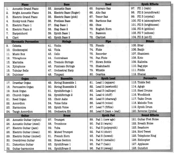
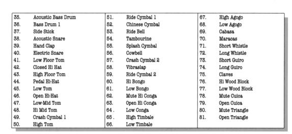
The core of the GM requirements is the Instrument Patch Map. This is a list of 128 sound presets, along with corresponding GM patch numbers. These patches fall into 16 groups of 8 instruments per group (see Table 3). GM also requires a defined set of Percussion Presets. There are 47 of these percussion instruments as described in Table 4.
In addition to the standardized sound set, GM instruments must support the following:
1. 24 voices of polyphony
2. Respond to all 16 MIDI channels
3. Each channel must be able to access any number of voices
4. Each channel must be able to play a different timbre
5. A full set of percussion instruments available on channel 10
6. All percussion instruments are mapped to specific MIDI note numbers
7. All sounds are available on all MIDI channels (except for channel 10)
8. All GM instruments and percussion respond to Note On velocity
9. Middle C is always note number 60
10. All GM instruments must respond to these MIDI controllers: 1-Modulation, 7-Volume, 10-Pan, 11-Expression, 64-Sustain Pedal, 121-Reset All Controllers and 123-All Notes Off
11. GM instruments must respond to all Registered Parameters: 0-Pitch Bend Sensitivity, 1-Fine Tuning and 2-Coarse Tuning.
12. GM instruments must respond to Channel Pressure (Aftertouch) and Pitch Bend.
|
|
|
Table 3. General MIDI Instrument Map. (Rona, 1994, p. 68) |
|
|
|
|
|
Table 4. General MIDI Percussion Map. (Rona,
1994, p. 69) |
Extensions to MIDI
Although the MIDI specification has remained essentially the same since 1984, there has been one major new standard to come along: the MIDI SDS (Sample Dump) Specification. This specification, adopted by the MMA in 1986, defines a standard method for the transfer of sound sample data (Withagen, n.d.).
There have also been a number of extensions provided by various manufacturers over the years. One of these, the GS Standard, developed by Roland, extended General MIDI by adding a larger set of sounds and provided macro control to synth parameters that controlled envelope attack and decay rates. Another synth manufacturer, Yamaha, recently announced XG-MIDI, yet another extension to GM. The MU-80, the first XG-MIDI product, includes 660 voices, compared to GM’s 128 (“The End of MIDI,” 1995).
The problem with these extensions is that they are specific to a given manufacturer’s product line, although they are downward compatible with GM. Hence, the XG-MIDI additional voices are not available on the Roland or any other synth. And it is unlikely that competing manufacturers will make XG-MIDI available on their product line unless the demand is sufficient to warrant the extra expense. Product specific extensions to MIDI will not work. What is needed is an extension to the existing protocol that can be incorporated into new equipment and still remain transparent to the existing equipment. The fundamental limitations of MIDI 1.0 need to be addressed in any future upgrade of the protocol. These basic limitations are:
1. Existing MIDI is only capable of directly addressing 16 devices due to the 16 channel limit imposed by the MIDI 1.0 standard.
2. The values used to describe most of the MIDI data are restricted to 128 levels, since most all the messages have data values stored in a single byte.
3. Although the original MIDI specification was never designed to handle timecode and machine control, the needs of the music community have changed and MIDI must evolve to meet these needs.
Xmidi (eXtended MIDI)
One possible, and very likely solution to the makeover that MIDI desperately needs is a new advanced enhancement of MIDI known as Xmidi. Xmidi, also referred to as XM or Extended MIDI, was developed by an application engineer in electronics named Eric Lukac-Kuruc. Lukac-Kuruc, who currently works for Digital Design & Development (DDD) of Belgium, proposed a hardware/software system designed to significantly enhance MIDI without changing the current specification (Maye, 1996). Many manufacturers are backing this new initiative, including Kurzweil, Oberheim, and E-mu.
What does Xmidi offer? For one, 324 channels of information and access to over 1.5 trillion controllers! It has a high speed mode, and can address over 700 billion presets. The data values are now able to extend to 510 vice the 127 of standard MIDI. And, it is bi-directional, so channel assignments can be made automatically and it can support checksums to acknowledge transmission of long blocks of data.
How is all this achieved? Xmidi uses ternary logic transmission capability (“The Theory Behind Xmidi,” n.d.). In this scheme, the off-state of binary bits is used optionally to turn on, or generate, reverse polarity current. This effectively replaces the two-state logic with three-state, or ternary logic. By taking advantage of these off-states in existing MIDI messages, Xmidi is capable of creating up to 13,122 new messages, all at no increase in bandwidth. All existing MIDI hardware is protected with a reverse polarized diode and cannot sense the reverse current, so this method is totally transparent to them and they can still operate in an Xmidi environment.
However, all of this comes with a price. As the first ever hardware upgrade to MIDI, there is the question of patents and fees for the use of the new chip as well as the cost of the new hardware. Although much of this is still undecided, the MMA and its members have been discussing the Xmidi issue for quite awhile. There is division among the ranks, and it seems for some reason, the MMA is against the new proposal. This is clearly indicated by their statement, back in mid-1995, in response to a request from DDD (“XMIDI: A Standard or Not?,” n.d.), “ ... that XMIDI was not likely to be adopted by the music products industry in the near future and that the MMA membership as a whole was not interested in establishing XMIDI as an industry adopted standard.” However, Xmidi offers the best, most cost effective solution to the MIDI upgrade problem, and it would seem that even the MMA will change their minds in the near future.
MIDI Implementation CHART
There is one final part of the MIDI specification. Although not really a true part of the MIDI standard, it is a much overlooked piece of documentation that is supplied by every manufacturer of MIDI sound equipment: the MIDI Implementation Chart.
Although MIDI made it possible for a wide variety of musical instruments and sound modules to communicate, this doesn’t mean that all MIDI instruments understand all of the MIDI language. In fact, few MIDI devices implement every variety of MIDI message. The MIDI specification only requires a core set of messages to be implemented. It was for this reason that the MIDI Implementation Chart was conceived and provided. This chart provides concise data showing the kinds of information that can be sent and received by the particular MIDI device. Part of such a chart is shown in Figure 6.
|
|
|
Figure 6. MIDI Implementation Chart. (“JV-1000 Music Workstation Sequencer Manual”, 1993) |

Conclusion
There is no doubt that MIDI, as a communications protocol, has been a huge success. Within three years after MIDI’s introduction, almost no electronic instrument was made in the world that didn’t have a MIDI port as part of its standard features (Rona, 1994). To this day there is no competing standard. Part of this success was certainly a result of good sound design (no pun intended!) The MIDI specification was designed with room to grow, and grow it did. Yet the electronics world has changed greatly since the introduction of MIDI. Computers are now faster, equipment is cheaper, and the demands on MIDI have now exceeded its ability to keep pace. Change is needed; a better MIDI is needed. Whether this will be Xmidi, or some other new standard yet to be developed is not certain. Xmidi is available now and provides solutions to all the immediate concerns and problems that have plagued MIDI 1.0 for years. But without MMA approval, acceptance of Xmidi is uncertain. What is certain is that musicians and sound engineers alike will continue to use MIDI well into the next century.
References
Heckroth, J. (1995). Tutorial on MIDI and Music Synthesis. [On-Line]. Available: http://datura.cerl.uiuc.edu/netstuff/midi/MMA/tutorial.html
Huber, D. M. (1991). The MIDI Manual. Carmel, Indiana: SAMS, Prentice Hall Computer Publishing.
JV-1000 Music Workstation Sequencer Manual. (1993). Roland Corporation.
Maye, J. (1996, January). Xmidi: MIDI gets a makeover. The MUSIC PAPER. [On-Line]. Available: http://ourworld.compuserve.com/homepages/eric_lukac_kuruc/musicpap.htm
MIDI From the Source. (n.d.). [On-Line]. Available: http://www.midi.org/specinfo.htm
MIDI Time Code. (n.d.). [On-Line]. Available: http://www.umr.edu/~johns/links/music/mtc.htm
Rona, J. (1994). The MIDI Companion. Milwaukee, Wisconsin: Hal Leonard Corporation.
Rothstein, J. (1995). MIDI: A Comprehensive Introduction. Madison, Wisconsin: A-R Editions, Inc.
The End of MIDI? FUTURE MUSIC. (1995). [On-Line]. Available: http://ourworld.compuserve.com/homepages/eric_lukac_kuruc/fm0495uk.htm
The MIDI Specification. (n.d.). [On-Line]. Available: http://www.umr.edu/~johns/links/music/midispec.htm
The Theory Behind Xmidi. (n.d.). [On-Line]. Available: http://ourworld.compuserve.com/homepages/eric_lukac_kuruc/xmtheory.htm
Withagen, H. (n.d.). SDS Specification. [On-Line]. Available: http://www.eeb.ele.tue.nl/midi/sds.html
XMIDI: A Standard or Not? (n.d.). [On-Line]. Available: http://www.midi.org/xmidi.htm